Best Design Tutorials

Design Tutorials provides the best and educational tutorials for your skills improvement

Wikipedia

Search results

Showing posts with label CorelDRAW X6. Show all posts
11:10:00

Working with Photoshop files in CorelDRAW® Graphics Suite

In this tutorial, we will be covering some of the most common tasks facing an Adobe Photoshop user who is transitioning to Corel® PHOTO-PAINT™. CorelDRAW Corel PHOTO-PAINT and Adobe Illustrator/Photoshop have many similarities and share some basic drawing and design capabilities, which makes it easy to move from one application to the other.

Have you been using Photoshop for a long time? If the answer is "Yes", you will probably want to continue working in an environment that is comfortable and familiar to you. Some users believe that transitioning to CorelDRAW means having to learn a program from scratch, or will mean a drastic change in the way they work. But the good news is that this is not necessary; you can continue working as usual, and even better.

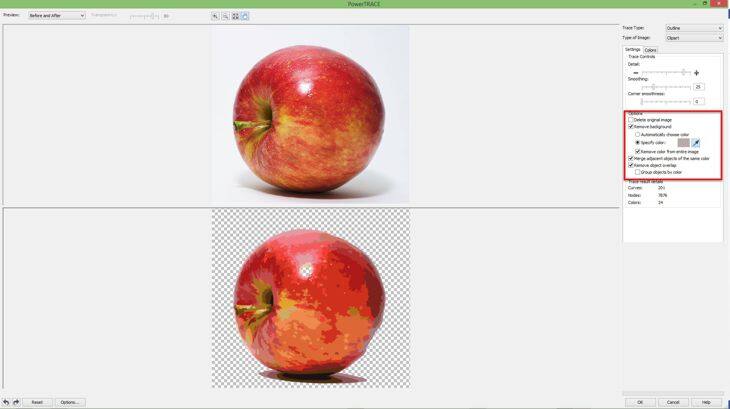
Moreover, you can work with both programs at the same time if you wish. CorelDRAW and Photoshop are good friends. Here we will provide some hints about how to work with both programs. Let's start with one of the basic and most frequent problems: removing the background from an image. Let's use as an example the image of an apple.

How do you remove the background image in Photoshop in preparation for bringing it into CorelDRAW? There are several ways of doing this, of course. For example, you can select the apple, and save the selection as a channel (Select > Save Selection... > select New Channel). That's all!
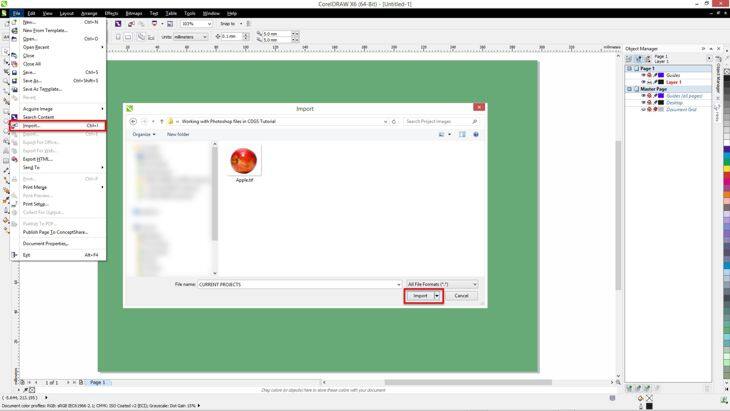
Now, save the image as a . TIF file (note: some file formats such as JPG do not support transparent backgrounds), then import the image into CorelDRAW using the command File > Import (Ctrl+I).


The Apple will have a transparent background. Fast and easy!


We can also use an alternative method. In Adobe Photoshop instead of saving the selection, create a new layer with a transparent background then save the image in the PSD format. That's all! Go back to CorelDRAW and choose the command File > Import (Ctrl+I) and select the. PSD file. CorelDRAW will recognize the transparent background.

Some Photoshop users prefer to use a Path (a vector mask) for this purpose. Again, this is no problem, if you already have an image with a saved Path or if you want to create a new one (by saving a selection as a Working Path) just go to File > Export > Paths to Illustrator.

Now, go back to CorelDRAW and import (File > Import), the saved path. The result will be an object without fill and without outline (and therefore invisible). But after importing it, and while the object is selected, choose any color on the Color Palette with the right mouse button to add a new outline.


If you've already deselected it, you can easily reselect it by pressing the tab key. Sometimes the new object is part of a "group", so you should first "ungroup" it (Ctrl+U).
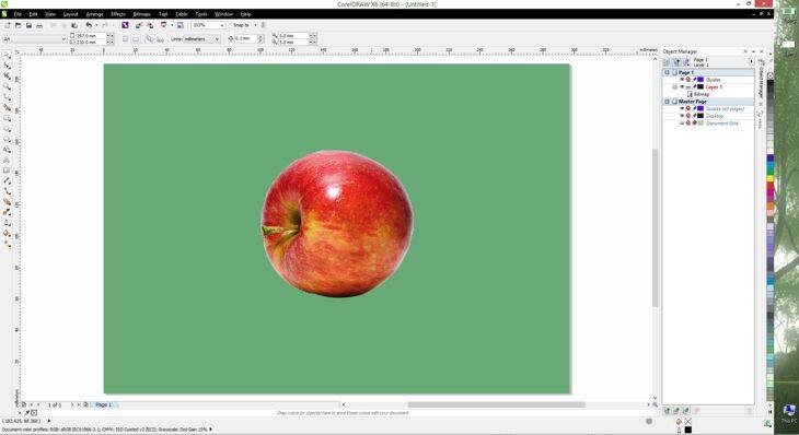
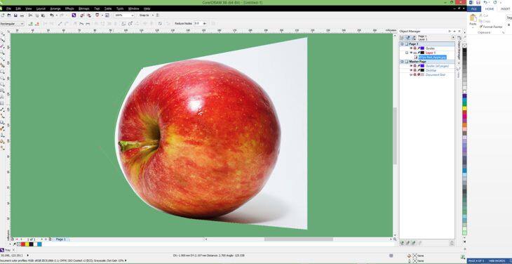
Now, import the Apple image, the original JPG, or a new file after correcting the image with Photoshop. Go to the Effects menu and select Powerclip > Place Inside Frame. An arrow cursor will appear. Click on the border of the path that you imported before, and the apple will be placed automatically inside the powerclip.


A power clip is not exactly the same as a "mask" in Illustrator, but it can be used in a similar way.
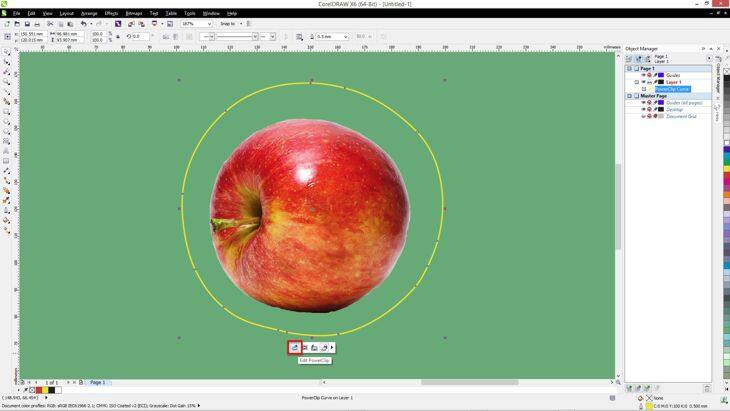
By default, the image should be centered within the powerclip. If the image is not in the correct position, you can reposition it (Alt+click), or you can edit the powerclip contents (Ctrl+click on the powerclip, or right-click the powerclip and choose "Edit Powerclip...") then move and/or resize the apple to fit within the border.


To return to the drawing page, click on "Stop editing contents".


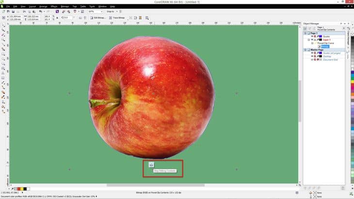
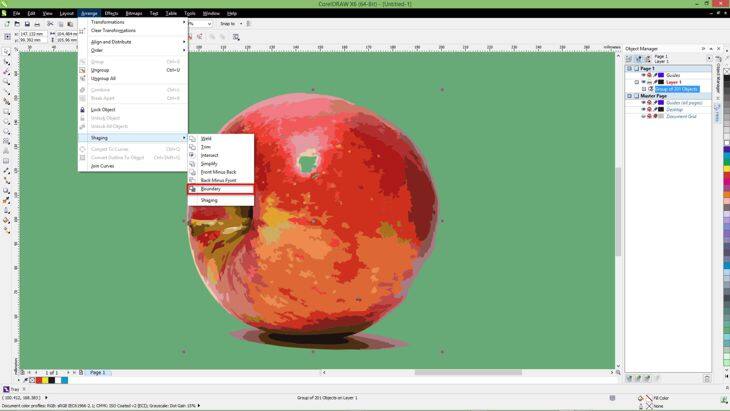
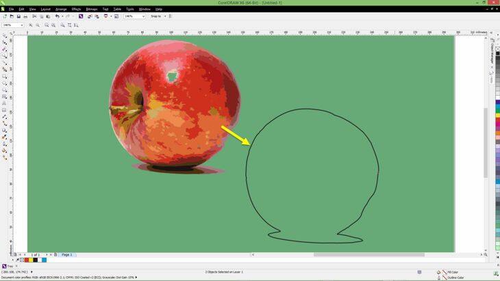
The difference between this last method and the previous two is that the edge in this case is a vector object. You can use the Shape Tool (F10) to correct or modify the object, add an outline, or any other effect you want to it.
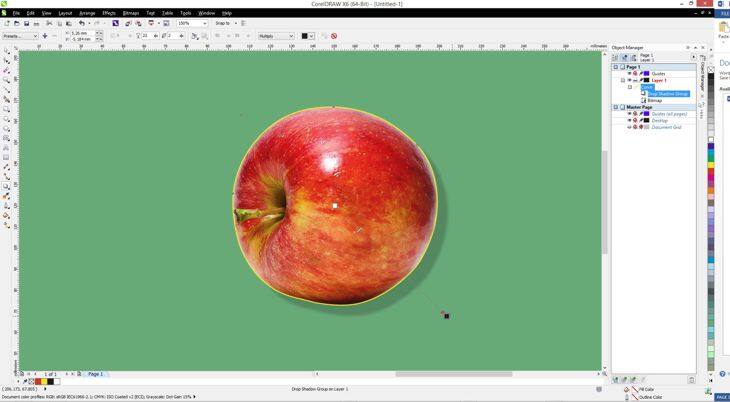
All three methods allow you to add a Drop Shadow, a Transparency (if you use Powerclip remember to apply the transparency to the image, not to the container object), and a lot of other effects.


But... do you need to use Photoshop at all if you can create a transparent background from within CorelDRAW? Not necessarily. CorelDRAW provides several tools for creating the same results.
Let's look at three of these: Import the Apple image in CorelDRAW using the command: File > Import, and with the right mouse button choose "Edit bitmap...". This will then open the image with Corel PHOTO-PAINT.


Corel PHOTO-PAINT is an image editor, similar in many aspects to Photoshop, but of course, there are also differences. The second tool in the Toolbox is a set of "selection" tools (hold the small black triangle next to the Rectangle Mask tool and you will see a fly-out menu with several other masking tools). The selection tools are called "Masks". These tools perform a similar function to the Marquee tools in Adobe Photoshop. There is a Rectangle Mask tool, Ellipse Mask, Freehand Mask, Magic Wand Mask, Brush Mask, etc. and in the Properties Bar settings, you can choose to add or subtract from the selection, etc.


The "Layers" here are called Objects. Despite these differences in names, you will soon feel at ease, but if remembering the command names in the Corel PHOTO-PAINT menus is inconvenient for you, well, there is a solution for everything. Go to Tools > Options > Workspace, and choose the Adobe Photoshop workspace.


In an instant, the program is organized in a way very similar to Photoshop, which will make it easier to use and learn.

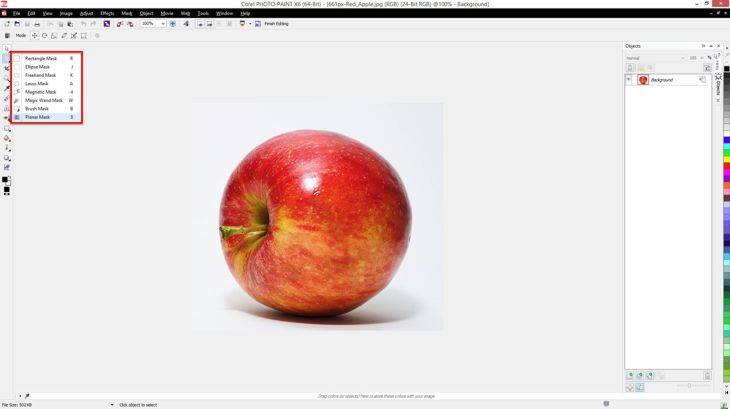
To create a transparent background, we can use a similar method as in Photoshop.
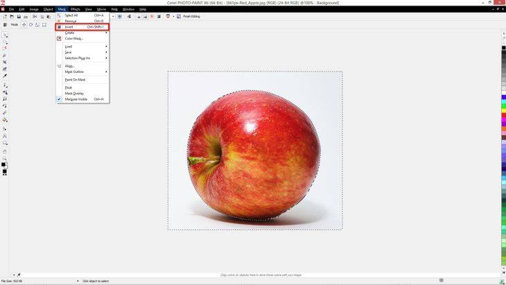
Select the image with the Mask tools, for example, the Magic Wand tool, to select the background. Since we want to select the apple, go to the "Mask" menu (remember, Mask = Select), and choose "Invert" (Mask > Invert or, CTRL+SHIFT+I).


That's all. Close PHOTO-PAINT, and when the program prompts you to save the file, choose 'Yes'. The image will return to CorelDRAW with transparent a background.
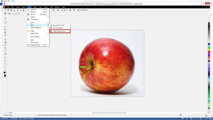
And yes, you can also save the selection in PHOTO-PAINT as an Alpha Channel from within the Mask menu (Mask > Save > Alpha Channel Save...), then save the image as a . CPT file (the native file format of Corel PHOTO-PAINT), .TIF, .PSD, etc. for later use.


But there are more ways to create a transparent background with CorelDRAW. Choose whichever way is best for you, relative to your workflow as a designer - and also which is relative to the image. If the image has a uniform background (white, for example), when you select the image choose "Color Mask" from the Mask menu. Then, using the Eyedropper tool in the Color Mask dialog box, you can select the background color, increase the tolerance, and remove the background color.


Here is another method of removing the background in CorelDRAW: Using the Shape tool (Toolbox > Shape tool) or (F10), select the bitmap and move the nodes of the image. Nodes can be added, deleted, converted to segments, to curves, or to straight segments... you can reshape the border as you need in a few steps!


Here is a final method I'd like to show you. You can draw an outline around the image with the Pen tool (F5), although there are several other types of drawing tools available. But perhaps don't want to draw a path manually? Select the image and choose "Trace Bitmap" on the Property Bar (or right-click on the object and choose a tracing method). Choose "Remove Background" while tracing the image. To remove the background entirely, check the box "Remove color from entire image". If the background consists of more than one color, select the "Specify Color" button and hold down the Shift key, use the Eyedropper tool to remove all areas of the background.


Now, selecting the traced objects, go to the Arrange menu > Shaping > Boundary.


This will give you the outline of the image, and you can use this as a container for power-clipping images. (Effects > PowerClip > Place Inside Frame...)
As you can see, as an Adobe Photoshop user, you can continue working as you did before, until you become familiar with the new tools of CorelDRAW. You will find many tools similar to those that you are accustomed to working with ... and more. You can use the same color settings in both programs to get the exact result you want (in CorelDRAW see: Tools > Color Management). But most importantly, you can feel confident in the knowledge that CorelDRAW is a safe choice for you to achieve your creative and professional goals.
11:09:00

How to turn a car design into a perspective drawing with CorelDRAW® X6

Using the Perspective tool, perspective deformation, and guidelines to create a sports car in one-point-perspective
This tutorial will demonstrate how a rough sketch of a car can be drawn in perspective with CorelDRAW. A basic knowledge of Guidelines, the Toolbox, and experience with drawing lines and curves is required.
The three views in the image below are aligned in such a way that the size and proportion of the car are consistent throughout all views. Whichever reference you use, pay the most attention to the wheels of the car, since they should be consistent, simple forms.


In this Perspective, I have decided to draw the car as seen from the left side, with a part of the top planes (the hood and the roof), visible. Regarding this presentation, ALL virtual lines are perpendicular to the side ‒ like the two axes connecting the wheels ‒ and converge to the one Vanishing Point that lies on the Horizon Line.
I need to place three additional Guidelines. They can be placed freely to restrict my drawing area: The Left Boundary, which is the very outer line of the left side of the car, and the Front and Back Boundaries, which indicate the very front and rear side of the car.


In order to retrieve the Right or far side Boundary, we draw a bounding rectangle around the car in Side View first. Move it down and enable View > Snap To > Snap to Guidelines and fit the lower left point to the intersection of the Front and Left Boundary. Resize the rectangle uniformly, until the bottom right corner is on the intersection of the Back and Left Boundary. The bottom side of the rectangle becomes the Left or near side Boundary.
Now we will use the Extrude Tool (Toolbox > Extrude tool), to create a box with a depth of 40 units, you can set this in the Properties Bar of the Extrude Tool. Make sure you drag from the center of the bounding rectangle copy to the Vanishing Point.


If you have no fills enabled, you will already see the far side bottom edge. Drag a Guideline from the Ruler and align it on the bottom far side edge. After that, you can delete the whole box, and we will later use more efficient tools for the perspective construction.
In Automotive Design, there are certain terms used throughout every design, which indicate the characteristics that all cars have in common, regardless of type and shape. In our design, we will indicate three major lines, which the Top and Side Views have in common, to help us in projecting points into perspective.
These lines are:
  • The Rocker Line (magenta) for the entire bottom line, starting at the front bumper and ending at the rear bumper.
  • The Greenhouse Line (blue) goes around all windows like the windshield, side windows, and rear shield.
  • The Shoulder Line and A-line (green) start at the front bumper, follow the hood go up the A-pillar, and follow the roof back over the trunk to the rear bumper. Notice that the Shoulder/A-Line doesn't necessarily follow the silhouette of the car, especially at the hood and the roof.


I've drawn these lines in Side View first and then copied and rotated them to match the Top View. With the Shape Tool and pressed the Ctrl Key I moved the nodes only on the horizontal axis, to ensure having the nodes matched the same position in Side and Top View in relation to the length of the car.
Since value changes in 2D indicate form changes in 3D, I only used my orthogonal sketches sporadically. I also added boundary rectangles and a centerline in the Top View. We will need the centerline later for symmetric projection purposes.
Once the Character Lines are established, I duplicate the Top View first, including the Character Lines and Boundary Rectangle, and rotate it by 90 degrees (use the rotation settings in the Property bar). In the duplicate, I created a boundary of the car for a clear silhouette, with Arrange > Shaping > Boundary.
With the Duplicate selected, I apply a perspective effect with Effects > Add Perspective, and move the four corners to match my Ground Plane.
The same is repeated for the Side View (except the perspective distortion), and I put the Side View Duplicate with the bottom edge onto the ground plane centerline (now correctly located in perspective).


For the wheels for our car I drew circles in dark grey (Toolbox > Ellipse tool or F7), making sure they match the Ground Plane Reference of the car silhouette as well as the position of the wheels in Centerline View (Centerline Section Cut, actually). An extrusion applied with the Extrude Tool (Toolbox > Extrude), changes the circles into wheels. Notice that I also played with the Bevel Settings in the Properties Bar.


The wheels need some rims too, but I'll not cover the creation of those here since it would be out of focus for this tutorial.


We will continue with the projection of the Character Lines of the car into perspective. I'll start with the magenta Rocker Line.
First, I created two additional Guidelines. One will end up in the Vanishing Point (the Rotation Center ‒ accessible by double-clicking on the Guideline ‒ needs to be moved and snapped onto the Vanishing Point). The second Guideline is used as a vertical axis to project the points up.
For each Node on the Rocker Line Curve, I follow a strict process:
  • I rotate the vanishing Guideline and let it snap on the Node of the Centerline Section Cut Rocker Line (Snap to Objects need to be enabled for this, (press ALT+Z). The Nodes are indicated with red circles in the bottom image.
  • I move the vertical Guideline and let it snap to the related Node in the Ground Plane Reference, on the Rocker Line Curve, next to the viewer.
  • Where both the vanishing Guideline and the vertical Guideline meet, the Node will be correctly located in the perspective construction.


This is repeated for each Node on the Rocker Line, for the near and the far side. By combining the two new curves and closing the front and back we now have the bottom of the car already!


The same process is also repeated for the Shoulder/A-Line Curve and the Greenhouse Line Curve.


The best practice would be to put all new shapes on separate Layers. This helps to keep the construction drawing clean by hiding layers individually.


I will continue with the overall silhouette of the perspective car drawing, but for that, I need the silhouette of the Centerline Section Cut (red) first.


To establish the overall silhouette, it is actually only a matter of connecting the endpoints of the planes, but after that, I go further and move some points due to the foreshortening of the far side of the perspective drawing.


Now I can estimate the location of the major forms like the windows and the windshield. If you are not sure, you can continue projecting points into the perspective of course, as we have done for the windshield, the hood bump, the fenders, and so on.


With the use of the Artistic Media Brushes (Toolbox > Artistic Media), and various Line Weights in the Outlines you can achieve very effective results in indicating forms. In the image below you can also see that I used the Ground Plane Reference as the shadow of the car, which provides a strong visual relationship to the ground. Cars usually don't levitate, right?


To be honest, the drawing looks a bit odd. That is due to the lack of a second Vanishing Point, which would be located down the vertical axis since we also look down onto the car in this projection. I also like to add a wide-lens distortion effect.
Create a boundary rectangle of the perspective drawing and convert it to curves (CTRL+Q). Move the bottom corners closer to each other, just a bit, to simulate a sense of vertical convergence. Then convert the Node type of all nodes to Curve Type in the Shape Tool Properties Bar, and drag the upper and lower edge slightly downwards, to achieve an arched look. The entire rectangle should now look like a bent screen in perspective.
Select the car again and go to the Envelope Tool (Toolbox > Envelope tool). In the Properties Bar click on the Eyedropper Icon (Create Envelope From) and click on the rectangle we created in the previous step.


The car is now distorted nicely. To make the effect visible, you need to move one of the envelope corners slightly.


Your car is ready for a ride now!
I have used the tools in this tutorial to provide a very flexible way of drawing in perspective. It is even possible to create drawings with two or more Vanishing Points.